How to Build a Grow Light Controller I/O Schedule
A controller ordering checklist for mapping grow light inputs, outputs, zones, sensors, fixture groups, and evidence owners before purchase approval.
A grow light controller I/O schedule should answer a purchasing question before the controller is ordered: which real fixture groups, sensors, zones, outputs, schedules, and fallback decisions does the controller need to handle? Treat the schedule as a buyer-owned control map, not as a generic product brochure. It should be clear enough for procurement, cultivation, engineering, and the installer to review before a 0-10V or RS485 controller is released for sample, shipment, or room rollout.
1. Start with zones, not product names
Begin with the control-zone plan: greenhouse bay, room, rack layer, bench, crop stage, blackout area, trial area, or maintenance zone. For each zone, list the fixture family, fixture count, dimming method, target operating window, sensor dependency, manual override need, and owner who can approve changes. This prevents a common ordering failure: buying a controller that looks correct on paper but has no row for the actual areas it must control.
2. Separate RS485 outputs from 0-10V outputs
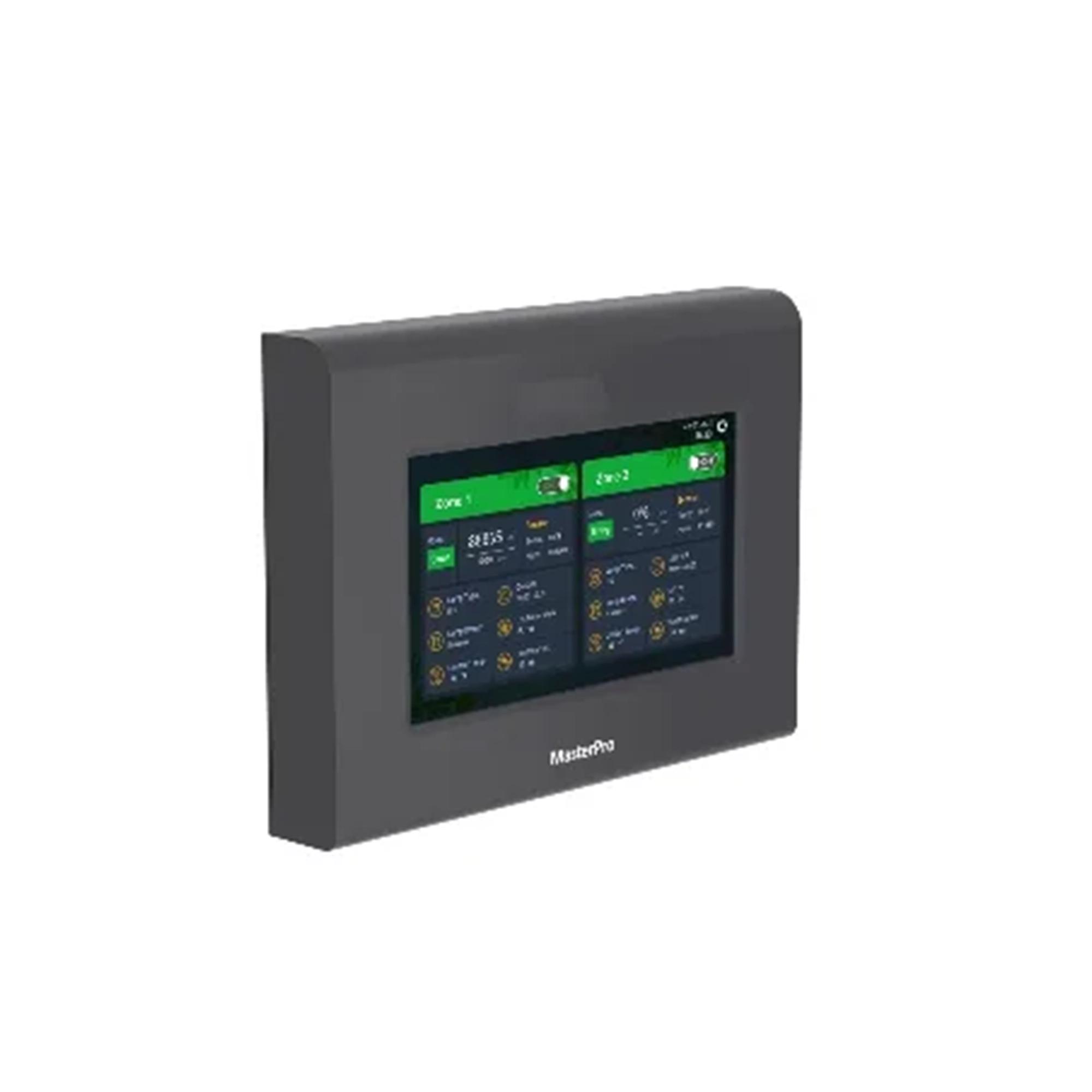
Current Sanity data lists the Master Pro Controller with 2-way RS485 output, 222 x 162 x 32 mm dimensions, 12 V / 1 A power from an included 100-240 VAC adapter, a 7 inch 1024 x 600 display, -20 C to 40 C and 0-90 percent RH operating range, IP54 protection, 20000 h listed lifespan, and a two-year warranty. Current Sanity data lists the LuxMind 3CH Controller with 12 V input, IP54 rating, 20000H average lifespan, and two groups of 0-10V dimming with RJ11, RJ45 3-channel dimming, and optional temperature sensor per group. Use these rows to choose the correct communication family and I/O map. Do not treat them as proof of final installation performance, crop response, certification status, or compatibility with every fixture in the room.
3. Give every input a reason and a fail state
The I/O schedule should name each sensor or input and explain why it exists. A useful row includes input type, physical location, crop or zone affected, control purpose, normal range, alarm threshold if used, action on missing signal, manual override owner, and whether the buyer expects the value to be logged. Optional temperature sensors, light sensors, time schedules, external interlocks, and cultivation overrides should not be left as vague notes. If a signal is important enough to change light output, the buyer should know what happens when that signal is unavailable.
4. Use external control guidance as context, not a listing claim
DLC NLC V5.2 describes networked lighting control strategies such as individual addressability, continuous dimming, zoning, high-end trim, photocell or daylight control, scheduling, scene control, energy monitoring, and related capabilities. The same page notes that horticultural control systems can be eligible as NLC systems when they meet DLC requirements, while DLC does not claim to qualify horticultural-specific capabilities. For a buyer, the practical takeaway is simple: document the required control functions and evidence rows, but do not call a controller or project DLC-qualified unless exact directory evidence is available for the system being claimed.
5. Tie schedules to DLI assumptions
Virginia Cooperative Extension frames supplemental lighting around average monthly DLI, PPFD at crop height, greenhouse light loss, and desired DLI. University of New Hampshire Extension turns the same idea into a runtime worksheet: additional light needed divided by lamp intensity times 0.0036 gives the hours to run. A controller I/O schedule should therefore include the buyer's schedule basis: crop stage, target photoperiod or DLI method, measured or assumed PPFD, daylight-sensor logic if used, and who can revise the schedule after observations. The schedule is a control assumption, not a yield promise.
6. Build one row per controlled output
For each controlled output, record zone name, controller model, output type, channel or RS485 bus reference, fixture group, fixture count, dimming range to be used, schedule name, sensor dependencies, manual override rule, alarm or exception action, cable or connector evidence owner, commissioning test owner, and unresolved assumptions. If one controller output feeds several fixture families or crop zones, split the row until the commercial risk is visible. A controller order should not rely on a single note that says all lights dim together.
Next step for a controller buyer
Before approving the controller purchase, ask Number to review one completed I/O schedule row for each different room, greenhouse bay, or rack type. The review should confirm the controller family, output type, fixture group, sensor dependency, schedule basis, and missing evidence. If any row is still unknown, hold it as an exception instead of burying it in a general controller note.