How to Specify Grow Light Controller Mounting and Power
A controller approval checklist for locking mounting, adapter power, IP rating, output ports, and handoff evidence before grow-room shipment.
A grow light controller is easy to under-specify because the buying discussion often jumps straight to channels, schedules, or sensor features. Before shipment, a commercial grow-room buyer should also lock the physical installation rows: where the controller mounts, how it is powered, which output ports are used, what environment the controller can tolerate, and what evidence the installer receives.
1. Start with the controller location
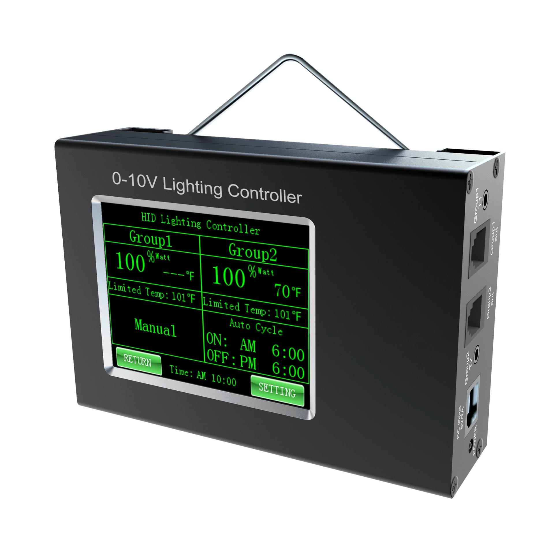
The current Number SLC Controller record lists dimensions of 222 x 162 x 32 mm and describes a compact, plug-and-play, hang-mountable unit. The current Number Master Pro Controller record lists the same 222 x 162 x 32 mm dimensions and a 7-inch 1024 x 600 display. Put those rows into the installation drawing before approving the controller, especially when the room has limited wall space, washdown routines, service aisles, or cabinet constraints.
2. Lock the adapter and low-voltage power row
Both current controller records list 12 V / 1 A power with a 100-240 VAC adapter included. Treat that as an approval row, not a footnote. The order sheet should state adapter input, controller-side power requirement, outlet or cabinet location, cable route, plug format if supplied separately, and who confirms the site power before commissioning. Do not assume a controller can be powered from a fixture circuit unless the wiring package explicitly says so.
3. Match output ports to the control method
The SLC product text describes two independent lighting zones via a single 0-10 V dimming output per channel. The Master Pro specification table lists 2-way RS485 output. Those are different approval paths. A 0-10 V project should identify each dimming channel, connector, fixture group, and maximum intended run. An RS485 project should identify address assignment, cable route, sensor input if used, and recovery behavior after power loss. If the fixture grouping is still unclear, complete the control-zone planning step before choosing the controller hardware.
4. Separate controller environment from fixture environment
A fixture IP rating does not automatically apply to a controller location. The current Master Pro record lists an operating range of -20 C to 40 C, 0-90% RH, and IP54 protection. The current SLC product record describes room-overheat protection, but its visible specification table only lists dimensions and power. Ask for model-specific environmental and mounting evidence when the controller will be placed near humid benches, service doors, spray zones, or climate equipment.
5. Require a shipment handoff packet
DesignLights Consortium Hort V3.0 is useful context because it treats dimming or control method details and connector or transmission hardware as product data that should be reported. For a controller order, request the same discipline: controller model, power adapter row, mounting method, port map, channel or address map, sensor row, fixture compatibility row, sample program if available, and acceptance checks for the first installed room. A product photo or menu screenshot is not enough evidence for shipment approval.
Approval checklist
Before releasing a controller shipment, approve seven rows: controller model, mounting location, adapter power, output protocol, fixture group map, environmental limits, and commissioning owner. That checklist keeps the controller discussion tied to verifiable product data and gives the installer the minimum evidence needed to make the first room reviewable.