How to Specify Sensor-Based RS485 Grow Light Control
A practical checklist for specifying RS485 grow light control with verified Master Pro specs, light-sensor logic, zone documents, and commissioning evidence.
Sensor-based RS485 grow light control is most useful when a project needs more than a timer: target light levels, sensor feedback, room protection logic, and a documented handoff between the lighting supplier, electrician, and cultivation team. The buying decision should start with the control objective, not the screen size or the number of menu options.
1. State what the controller is allowed to decide
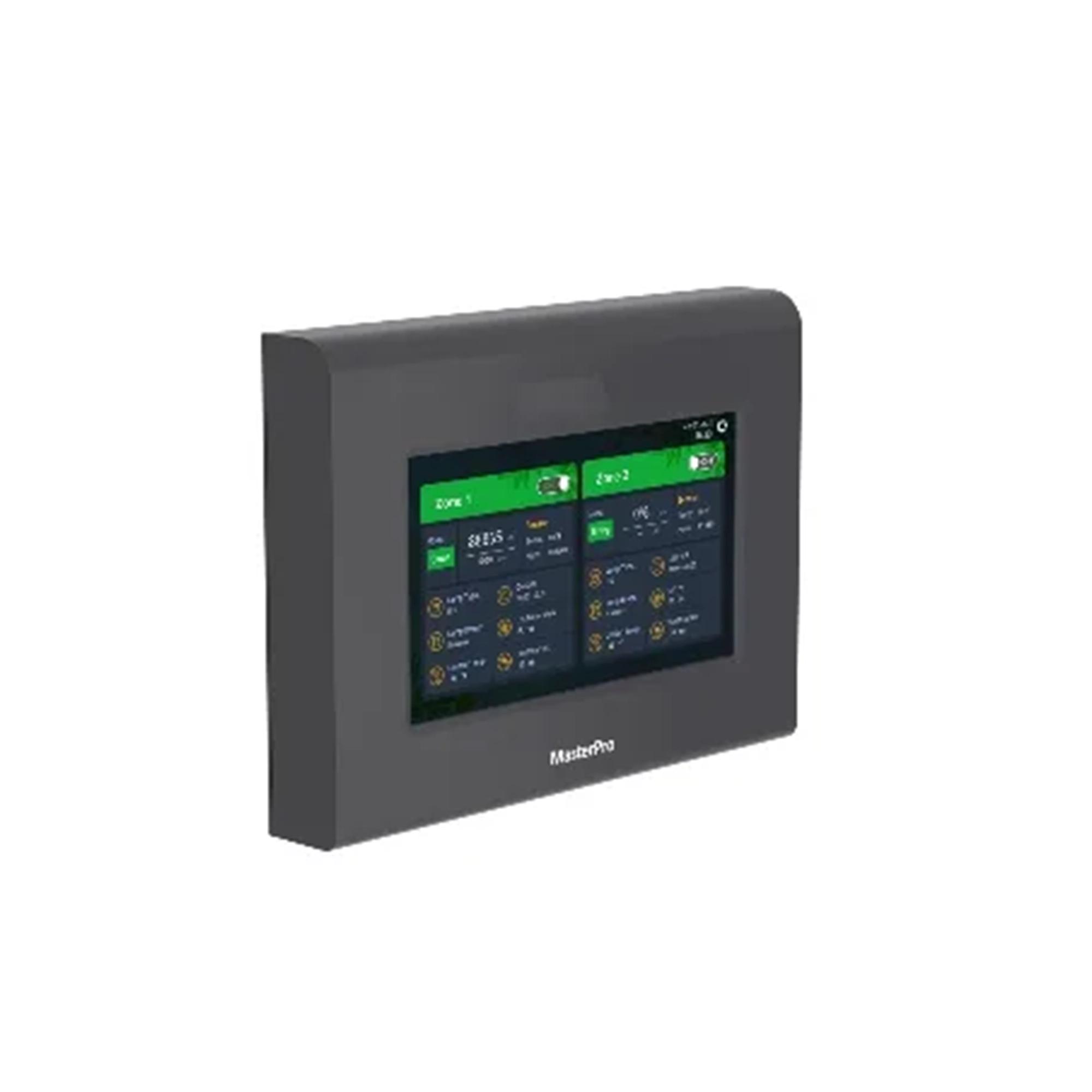
The Number Master Pro RS485 controller is listed in Sanity with 2-way RS485 output. Its product description says output is automatically adjusted according to the set time period, targeted lighting intensity, and lighting intensity collected by sensor. That aligns with the control concept described by University of Missouri Extension, which notes that sensors can measure sunlight to estimate whether supplemental lighting is needed. For procurement, write down whether the controller may dim lights, turn lights off, hold a minimum output, or only alert the operator.
2. Convert crop intent into measurable light rules
A controller cannot rescue an unclear lighting plan. Record target photoperiod, target canopy PPFD range, blackout constraints, acceptable ramp behavior, and who will review DLI after commissioning. Virginia Tech Extension defines DLI as the amount of photosynthetic light reaching the plant over a 24-hour period, so the control sequence should be checked against the crop plan rather than treated as a generic automation feature.
3. Verify the RS485 wiring and fixture-control match
Before ordering, confirm that each fixture, driver, or interface module supports the same RS485 control approach, then document address assignment, cable route, controller location, sensor location, and recovery behavior after power loss. If the room still needs to define which fixtures change together, use a control-zone drawing before selecting hardware; the earlier 0-10 V and RS485 control-zone checklist covers that planning step.
4. Treat controller specs as installation limits
The current Master Pro Sanity record lists 222 x 162 x 32 mm dimensions, 12 V / 1 A power from an included 100-240 VAC adapter, a 7 inch 1024 x 600 display, IP54 protection, a -20 C to 40 C operating range, 0-90 %RH operating humidity, 20000 h lifespan, and a 2-year warranty. These values help place and protect the controller. They do not define fixture load, branch-circuit design, crop response, or compliance for the full installation.
5. Write down the over-temperature sequence
The Master Pro description says that when detected environmental temperature exceeds the setting value, light output will be off until temperature recovers. That is a protection behavior, not a complete climate-safety plan. The project specification should state where temperature is measured, who sets the threshold, what message appears to staff, and whether the climate controller or alarm system has a separate response.
6. Ask for control evidence before shipment
DLC horticultural technical requirements include controllability and reporting context for LED horticultural products, including dimming and control-method details. For an RS485 control package, request the fixture-control method, wiring diagram, sensor model or input definition, sample program, address map, and commissioning checklist. Do not accept a controller photo as evidence that the full room sequence has been validated.
When to involve the OEM team
Bring the Number OEM/ODM team into the discussion when the project needs custom fixture communication, private-label control documentation, alternate sensor placement, or a room-specific wiring package. The smallest useful evidence asset is a one-page control sequence that names the fixture model, protocol, sensor inputs, thresholds, and acceptance test for the sample room.